| BS 5308 Cables | |||
| BS5308 Part 1 / Type 1 | BS5308 Part 1 / Type 2 | BS5308 Part 2 / Type 1 |
BS 5308 Cables
BS5308 Part 1
BS5308 Part 1 / Type 1 (unarmoured cables)
BS5308 Cable Part 1 Type 2 MG-XLPE-OS-SWA-LSOH
Application
The armoured fire resistant versions (Part 1Type 1) are typically used in chemical and process
industries where there is danger of fire. The galvanised steel wire armour provides excellent protection.
Construction
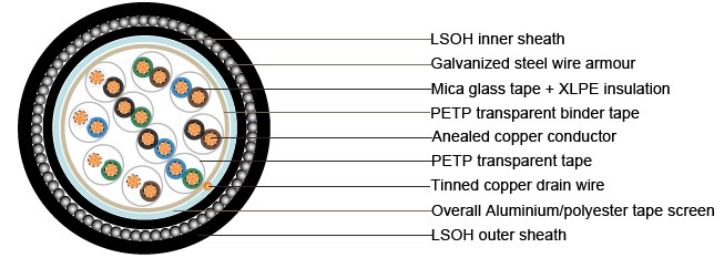
Conductor |
Annealed copper, Class 2 |
Insulation |
Mica glass tape, XLPE (Cross Linked Polyethylene), or PE (optional) |
Pairing |
Two insulated conductors uniformly twisted together with a lay not exceeding 100mm |
Colour code |
See technical information |
Binder tape |
PETP transparent tape |
Collective screen |
Aluminium/polyester tape is applied over the laid up pairs metallic side down in contact with tinned copper drain wire, 0.5mm² |
Inner Sheath |
LSOH(Low Smoke Zero Halogen) sheath |
Amour |
Galvanized steel wire armour |
Outer sheath |
LSOH(Low Smoke Zero Halogen) sheath Flame retardant to IEC60332-3-22 Fire resistant to IEC60331 Halogen free to IEC60754-1 Low smoke emission to IEC61034-1-2 |
Sheath colour |
Black or blue |
Mechanical and Electrical Properties
Operating temperature: -20˚C up to + 90˚C( fixed installation) 0˚C to +50˚C(during operation ) Minimum bending radius: 6 x overall diameter
Conductor Area Size |
mm2 |
0.5 |
0.75 |
1.0 |
1.5 |
|
Conductor Stranding |
No. x mm |
7 x 0.3 |
7 x 0.37 |
7 x 0.43 |
7 x 0.53 |
|
Conductor resistance max |
ohm/km |
39 |
24.5 |
18.1 |
12.1 |
|
Insulation resistance min |
Gohm/km |
5 |
5 |
5 |
5 |
|
Capacitance unbalance at 1 kHz(pair to pair screen) |
pF/250m |
|
250 |
|
||
Max. Mutual Capacitance @ 1 kHz forNon OS or OS cables (except one-pair and two-pairs) |
pF/m |
115 |
115 |
115 |
115 |
|
Max. Mutual Capacitance @ 1 kHz IS/OS cables (include 1 pair and 2 pair) |
pF/m |
75 |
75 |
75 |
75 |
|
Max. L/R Ratio for adjacent cores(Inductance/Resistance) |
μH/ohm |
25 |
25 |
25 |
40 |
|
Test voltage |
Core to core |
V |
1000 |
1000 |
1000 |
1000 |
Core to screen |
V |
1000 |
1000 |
1000 |
1000 |
|
Rated voltage max |
V |
300/500 |
300/500 |
300/500 |
300/500 |
|
No.of Pairs |
No.and Dia. of Wires |
Nominal Conductor Cross-Sectional Area |
Nominal Thickness of Insulation |
Nominal Thickness of bedding |
Nominal Dia. over Bedding |
Nominal Thickness of Armour |
Nominal Thickness of Sheath |
Nominal Dia. of Cable |
Approx.Weight |
|
no./mm |
mm2 |
mm |
mm |
mm |
mm |
mm |
mm |
kg/km |
1 |
7/0.43 |
1 |
0.6 |
0.8 |
7.0 |
0.9 |
1.4 |
11.6 |
340 |
2 |
7/0.43 |
1 |
0.6 |
0.8 |
8.4 |
0.9 |
1.4 |
13.0 |
350 |
5 |
7/0.43 |
1 |
0.6 |
0.8 |
12.3 |
0.9 |
1.4 |
16.9 |
740 |
10 |
7/0.43 |
1 |
0.6 |
0.8 |
16.5 |
0.9 |
1.4 |
21.1 |
1150 |
20 |
7/0.43 |
1 |
0.6 |
0.8 |
21.4 |
0.9 |
1.4 |
26.0 |
1840 |
1 |
7/0.53 |
1.5 |
0.6 |
0.8 |
7.5 |
0.9 |
1.4 |
11.9 |
320 |
2 |
7/0.53 |
1.5 |
0.6 |
0.8 |
9.1 |
0.9 |
1.4 |
13.7 |
410 |
5 |
7/0.53 |
1.5 |
0.6 |
0.8 |
14.8 |
0.9 |
1.4 |
21.1 |
910 |