| Fire Resistant Cable | |||
![]() Fire Resistant Cable
Fire Resistant Cable
300/500V Mica+XLPE Insulated Individual And Overall Screened Instrumentation CablesRE-2X(St)H PiMF...CI. FE 180 PH30 ( CU/MGT+XLPE/PSCR/OSCR/LSZH 300/500V Class 2 )
|
|||||||||||||||||||||||||||||||||||||||||||||||||||||||||||||||||||||||||||||||||||||||||||||||||||||||||||||||||||||||||||||||||||||||||||||||||||||||||||||||||||||||||||||||||||||||||||||||||||||||||||
Circuit Integrity |
IEC 60331-21; BS 6387 CWZ; DIN VDE 0472-814(FE180); |
Circuit Integrity with mechanical shock |
EN 50200(PH30); CEI 20-36/4-0 |
Circuit Integrity with mechanical shock & water spray |
EN 50200 annex E |
System circuit integrity |
DIN 4102-12, E30 depending on lay system |
Flame Retardance (Single Vertical |
EN 60332-1-2; IEC 60332-1-2; BS EN 60332-1-2; |
Reduced Fire Propagation |
EN 60332-3-24 (cat. C); IEC 60332-3-24; BS EN 60332-3-24; VDE 0482-332-3; NBN C 30-004 (cat. F2); NF C32-070-2.2(C1); CEI 20-22/3-4; EN 50266-2-4*; DIN VDE 0482-266-2-4 |
Halogen Free |
IEC 60754-1; EN 50267-2-1; DIN VDE 0482-267-2-1; CEI 20-37/2-1 ; BS 6425-1* |
No Corrosive Gas Emission |
IEC 60754-2; EN 50267-2-2; DIN VDE 0482-267-2-2; CEI 20-37/2-2 ; BS 6425-2* |
Minimum Smoke Emission |
IEC 61034-1&2; EN 61034 -1&2; DIN VDE 0482-1034-1&2; CEI 20-37/3-1&2; EN 50268-1&2*; BS 7622-1&2* |
No Toxic gases |
NES 02-713; NF C 20-454 |
Note: Asterisk * denotes superseded standard.
VOLTAGE RATING
300/500 V
CABLE CONSTRUCTION
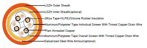
Conductor: Plain annealed copper wire, stranded according to IEC(EN) 60228 class 2.
Insulation: Mica glass tape covered by extruded cross-linked XLPE compound or fire resistant
silicone rubber compound type EI2 as per BS 7655-1.1.
Cabling Elements: Insulated cores are twisted to form pairs with varying lay length to minimize
crosstalk. Two-pair cable had four cores laid in quad formation.
Cabling: Pairs are cabled together.In cables with 8 pairs or more, 4 pairs are assembled to form a
bunch, the bunches are then cabled together.
Individual Screen: Aluminum/polyester tape with 0.5mm2 screen (7/0.3mm) tinned copper drain
wire.
Overall Screen: Aluminum/polyester tape with 0.5mm2 screen (7/0.3mm) tinned copper drain wire.
Inner Sheath(optional): Thermoplastic LSZH compound type LTS3 as per BS 7655-6.1
Armouring(optional): Galvanized steel wire armour
Outer Sheath: Thermoplastic LSZH compound type LTS3 as per BS 7655-6.1( Thermosetting LSZH
compound type SW2-SW4 as per BS 7655-2.6 can be offered.)
COLOUR CODE
Insulation Colour: White with black numberings.
Sheath Colour: Orange (other colours on request).
TYPE CODE
RE- Instrumentation cable H Halogen free & zero halogen
2X XLPE 2G Silicon Rubber
(St) Static shield of aluminium tape SWA Steel Wire Armoured
FE180 Insulation integrity (950°C 180 minutes) CI Circuit integrity
PH 90 Fire Test for 90 mins at 830°C
Physical AND THERMAL PROPERTIES
Temperature range during operation (fixed state): -30°C – +70°C
Temperature range during installation (mobile state): -20°C – +50°C
Minimum bending radius: 6 x Overall Diameter (unarmoured cables with silicone rubber insulation)
8 x Overall Diameter (unarmoured cables with XLPE insulation)
10 x Overall Diameter (armoured cables)
Electrical PROPERTIES
Dielectric test: |
2000 V r.m.s. x 5' (core/core) |
Insulation resistance |
≥1000 MΩ x km (at 20°C); |
Short circuit temperature |
XLPE: 250°C |
CONSTRUCTION PARAMETERS
Conductor
|
RE-2X(St)H
PiMF...CI. FE 180
PH30 RE-2G(St)H PiMF...CI. FE 180 PH30 |
RE-2X(St)HSWAH PiMF..CI. FE 180 PH30 |
||||||
| No. of Pairs X Cross Section |
No./ Nominal Diameter of Strands | Nominal Insulation Thickness | Unarmoured | Armoured | ||||
| Nominal Overall Diameter | Approx. Weight | Diameter Under Armour | Armour Wire Diameter | Nominal Overall Diameter | Approx. Weight | |||
mm2 |
no./mm |
mm |
mm |
kg/km |
mm | mm | mm | kg/km |
2 Pairs |
||||||||
2X2x1.0 |
7/0.43 |
0.6 |
15.2 |
166 |
15.2 |
0.90 |
20.0 |
555 |
2X2x1.5 |
7/0.53 |
0.7 |
17.0 |
205 |
17.0 |
1.25 |
22.7 |
769 |
2X2x2.5 |
7/0.67 |
0.8 |
19.2 |
350 |
19.2 |
1.25 |
24.9 |
938 |
5 Pairs |
||||||||
5X2x1.0 |
7/0.43 |
0.6 |
17.5 |
335 |
17.5 |
1.25 |
23.2 |
1000 |
5X2x1.5 |
7/0.53 |
0.7 |
21.5 |
433 |
21.5 |
1.60 |
28.1 |
1352 |
5X2x2.5 |
7/0.67 |
0.8 |
24.0 |
592 |
24.0 |
1.60 |
30.8 |
1665 |
10 Pairs |
||||||||
10X2x1.0 |
7/0.43 |
0.6 |
22.5 |
626 |
22.5 |
1.60 |
29.3 |
1800 |
10X2x1.5 |
7/0.53 |
0.7 |
28.0 |
811 |
28.0 |
1.60 |
35.0 |
2165 |
10X2x2.5 |
7/0.67 |
0.8 |
31.5 |
1132 |
31.5 |
2.00 |
39.5 |
3007 |
| 20 Pairs | ||||||||
20X2x1.0 |
7/0.43 |
0.6 |
30.5 |
1143 |
30.5 |
2.00 |
38.5 |
3019 |
20X2x1.5 |
7/0.53 |
0.7 |
38.0 |
1509 |
38.0 |
2.00 |
46.2 |
3684 |
20X2x2.5 |
7/0.67 |
0.8 |
42.5 |
2112 |
42.5 |
2.50 |
51.9 |
5107 |
Note : Other conductor sizes & core configurations are available upon request.