| FIREGUARD Flame Retardant Cables | |||
![]() Flame Retardant Data Cables
Flame Retardant Data Cables
Flame Retardant CAT6 Data CablesFGD-CAT6 U/UTP4P23
|
Flame Retardance (Single Vertical |
EN 60332-1-2; IEC 60332-1-2; BS EN 60332-1-2; VDE |
Reduced Fire Propagation |
EN 60332-3-24 (cat. C); IEC 60332-3-24; BS EN 60332-3-24; VDE 0482-332-3; NBN C 30-004 (cat. F2); NF C32-070-2.2(C1); CEI 20-22/3-4; EN 50266-2-4*; DIN VDE 0482-266-2-4 |
Note: Asterisk ** denotes that the standard compliance is optional, depending on the oxygen index of the PVC compound and the cable design.
VOLTAGE RATING
60V
CABLE CONSTRUCTION
Conductors: 23AWG solid bare copper.
Insulation: HDPE.
Twinning: Two coloured insulated conductors twisted together to form a pair.
Outer Sheath: Thermoplastic PVC compound. UV resistance, hydrocarbon resistance, oil
resistance, anti rodent and anti termite properties can be offered as option. Compliance to fire
performance standard (IEC 60332-1, IEC 60332-3, UL 1581, UL 1666 etc) depends on the oxygen
index of the PVC compound and the overall cable design. LSPVC can also be provided upon
request.
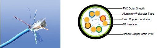
Cat6 F/UTP: These cables have collective shielding of aluminium/Polyester tape with drain wire.
Cat6 SF/UTP: These cables have double collective shieldings of aluminium/Polyester tape &
copper wire braid with drain wire.
Physical AND THERMAL PROPERTIES
Temperature range: -30°C ~ +75°C
Minimum bending radius during installation (mobile state): 8 x Overall Diameter
Minimum bending radius during operation (fixed state): 4 x Overall Diameter
Electrical Properties
AWG |
|
23 |
Nominal Conductor Diameter |
mm |
0.56/0.57/0.58 |
Maximum DC Resistant@20°C |
Ω/100m |
9.38 |
Maximum DCR Unbalance |
% |
3 |
Maximum Mutual Capacitance |
pF/m |
5.8 |
Maximum Capacitance Unbalance |
pF/100m |
30 |
Characteristic Impedance@1-100MHz |
Ω |
100+/-15 |
Maximum Propagation Delay Skew |
ns/100m |
18 |
Transmission Properties
FREQ MHz |
Maximum |
Minimum |
Minimum |
Minimum |
Minimum |
Minimum |
0.772 |
1.8 |
76.0 |
74. |
70.0 |
67.0 |
— |
1 |
2.0 |
74.3 |
72.3 |
67.8 |
64.8 |
20.0 |
4 |
3.8 |
65.3 |
63.3 |
55.7 |
52.7 |
23.0 |
8 |
5.3 |
60.8 |
58.8 |
49.7 |
46.7 |
24.5 |
10 |
6.0 |
59.3 |
57.3 |
47.8 |
44.8 |
25.0 |
16 |
7.6 |
56.3 |
54.3 |
43.7 |
40.7 |
25.0 |
20 |
8.5 |
54.8 |
52.8 |
41.7 |
38.7 |
25.0 |
25 |
9.5 |
53.3 |
51.3 |
39.8 |
36.8 |
24.3 |
31.25 |
10.7 |
51.9 |
49.9 |
37.9 |
34.9 |
23.6 |
62.5 |
15.4 |
47.4 |
45.4 |
31.8 |
28.8 |
21.5 |
100 |
19.8 |
44.3 |
42.3 |
27.8 |
24.8 |
20.1 |
155 |
25.2 |
41.5 |
39.5 |
23.9 |
20.9 |
18.8 |
200 |
29.0 |
39.8 |
37.8 |
21.7 |
18.7 |
18.0 |
250 |
32.8 |
38.3 |
36.3 |
19.8 |
16.8 |
17.3 |
CONSTRUCTION PARAMETERS
Cable Code |
Conductor |
Diameter Over Insulation |
Pairs |
Screen |
Overall |
|
mm |
mm |
|
|
mm |
FGD-Cat6 U/UTP |
0.56/0.57 |
1.02 |
4 |
Nil |
6.0 |
FGD-Cat6 F/UTP |
0.57/0.58 |
1.02 |
4 |
Overall Aluminum Tape Screen |
6.3 |
FGD-Cat6 SF/UTP |
0.57/0.58 |
1.02 |
4 |
Overall Aluminum Tape Screen & Copper Wire Braid |
6.6 |