| FIREGUARD Flame Retardant Cables | |||
![]() Flame Retardant Instrumentation Cables
Flame Retardant Instrumentation Cables
Flame Retardant Individual and Overall Screened Instrumentation Cables (Multipair)RE-2X(St)Y PiMF |
||||||||||||||||||||||||||||||||||||||||||||||||||||||||||||||||||||||||||||||||||||||||||||||||||||||||||||||||||||||||||||||||||||||||||||||||||||||||||||||||||||||||||||||||||||||||||||||||||||||||||||||||||||||||||||||||||||||||||||||||||||||||||||||||||||||||||||||||||||||||||||||||||||||||||||
Flame Retardance (Single Vertical |
EN 60332-1-2; IEC 60332-1-2; BS EN 60332-1-2; VDE |
Reduced Fire Propagation |
EN 60332-3-24 (cat. C); IEC 60332-3-24; BS EN 60332-3-24; VDE 0482-332-3; NBN C 30-004 (cat. F2); NF C32-070-2.2(C1); CEI 20-22/3-4; EN 50266-2-4*; DIN VDE 0482-266-2-4 |
Note: Asterisk ** denotes that the standard compliance is optional, depending on the oxygen index of the PVC compound and the cable design.
VOLTAGE RATING
300/500V
CABLE CONSTRUCTION
Conductor: Annealed or tinned copper, sizes: 0.5mm² and 0.75mm² mulitistranded(Class 5), 0.5
mm², 1.0 mm² solid(Class 1), 1.5mm² or 2.5mm², multistranded(Class 2) to BS6360
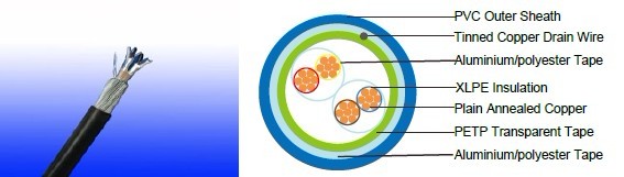
Insulation: XLPE (Cross Linked Polyethylene), or PE (optional)
Pairs: Two insulated conductors uniformly twisted together with a lay not exceeding 100mm
Individual Screen: Aluminium/polyester tape is applied over each pair metallic side down in contact
with tinned copper drain wire, 0.5mm²
Binder tape: PETP transparent tape
Overall Screen: Aluminium/polyester tape is applied over the laid up pairs metallic side down in
contact with tinned copper drain wire, 0.5mm²
Outer Sheath: Thermoplastic PVC compound. UV resistance, hydrocarbon resistance, oil resistance,
anti rodent and anti termite properties can be offered as option. Compliance to fire performance
standard (IEC 60332-1, IEC 60332-3, UL 1581, UL 1666 etc) depends on the oxygen index of the
PVC compound and the overall cable design. LSPVC can also be provided upon request.
COLOUR CODE
Insulation Colour: See technical information
Outer sheath: Black or blue
Physical AND THERMAL PROPERTIES
Maximum Operating temperature: -20˚C - + 90˚C( fixed installation)
0˚C - +50˚C(during operation)
Minimum bending radius: 5 x Overall Diameter
Electrical Properties
Conductor Area Size |
mm 2 |
0.5 |
0.5 |
0.75 |
1.0 |
1.5 |
|
Conductor Stranding |
No. x mm |
1 x 0.8 |
16 x 0.2 |
24 x 0.2 |
1 x 1.13 |
7 x 0.53 |
|
Conductor resistance max |
ohm/km |
36.8 |
39.7 |
26.5 |
18.2 |
12.3 |
|
Insulation resistance min |
Gohm/km |
5 |
5 |
5 |
5 |
5 |
|
Capacitance unbalance at 1 kHz(pair to pair screen) |
pF/250m |
250 |
|||||
Max. Mutual Capacitance @ 1 |
pF/m |
115 |
115 |
115 |
115 |
115 |
|
Max. Mutual Capacitance @ |
pF/m |
75 |
75 |
75 |
75 |
75 |
|
Max. L/R Ratio for adjacent cores(Inductance/Resistance) |
μH/ohm |
25 |
25 |
25 |
25 |
40 |
|
Test voltage |
Core to core |
V |
1000 |
1000 |
1000 |
1000 |
1000 |
Core to screen |
V |
1000 |
1000 |
1000 |
1000 |
1000 |
|
Rated voltage max |
V |
300/500 |
300/500 |
300/500 |
300/500 |
300/500 |
|
CONSTRUCTION PARAMETERS
Number of Pairs |
No./ |
Nominal Conductor Cross- Section Area |
Nominal Insulation Thickness |
Nominal Sheath Thickness |
Nominal Overall Diameter |
Approx. Weight |
No./mm |
mm2 |
mm |
mm |
mm |
kg/km |
|
2 |
1/0.8 |
0.5 |
0.5 |
0.9 |
9.7 |
95 |
5 |
1/0.8 |
0.5 |
0.5 |
1.2 |
13 |
180 |
10 |
1/0.8 |
0.5 |
0.5 |
1.2 |
16.9 |
310 |
15 |
1/0.8 |
0.5 |
0.5 |
1.3 |
19.7 |
440 |
20 |
1/0.8 |
0.5 |
0.5 |
1.3 |
22.3 |
560 |
30 |
1/0.8 |
0.5 |
0.5 |
1.5 |
27.1 |
820 |
50 |
1/0.8 |
0.5 |
0.5 |
2 |
35 |
1370 |
2 |
16/0.2 |
0.5 |
0.6 |
1.1 |
11.2 |
110 |
5 |
16/0.2 |
0.5 |
0.6 |
1.2 |
14.5 |
250 |
10 |
16/0.2 |
0.5 |
0.6 |
1.3 |
19.3 |
480 |
15 |
16/0.2 |
0.5 |
0.6 |
1.5 |
22.6 |
570 |
20 |
16/0.2 |
0.5 |
0.6 |
1.5 |
25.7 |
780 |
30 |
16/0.2 |
0.5 |
0.6 |
1.7 |
31 |
1020 |
50 |
16/0.2 |
0.5 |
0.6 |
2.2 |
39.9 |
1680 |
2 |
1/1.13 |
1 |
0.6 |
1.1 |
11.9 |
200 |
5 |
1/1.13 |
1 |
0.6 |
1.2 |
15.4 |
290 |
10 |
1/1.13 |
1 |
0.6 |
1.3 |
20.5 |
580 |
15 |
1/1.13 |
1 |
0.6 |
1.5 |
24.1 |
780 |
20 |
1/1.13 |
1 |
0.6 |
1.7 |
27.7 |
1010 |
30 |
1/1.13 |
1 |
0.6 |
2 |
33.7 |
1430 |
50 |
1/1.13 |
1 |
0.6 |
2.2 |
42.5 |
2360 |
2 |
7/0.53 |
1.5 |
0.6 |
1.2 |
13.6 |
250 |
5 |
7/0.53 |
1.5 |
0.6 |
1.3 |
17.7 |
460 |
10 |
7/0.53 |
1.5 |
0.6 |
1.5 |
23.9 |
760 |
15 |
7/0.53 |
1.5 |
0.6 |
1.7 |
28 |
1020 |
20 |
7/0.53 |
1.5 |
0.6 |
2 |
31.7 |
1350 |
30 |
7/0.53 |
1.5 |
0.6 |
2.2 |
38.6 |
1900 |
50 |
7/0.53 |
1.5 |
0.6 |
2.2 |
48.9 |
3060 |