| FIREGUARD Flame Retardant Cables | |||
![]() Flame Retardant Instrumentation Cables
Flame Retardant Instrumentation Cables
Flame Retardant Overall Screened Instrumentation Cables (Multicore)RE-2X(St)Y
|
||||||||||||||||||||||||||||||||||||||||||||||||||||||||||||||||||||||||||||||||||||||||||||||||||||||||||||||||||||||||||||||||||||||||||||||||||||||||||||||||||||||||||||||||||||||||||||||||||||||||||||||||||||||||||||||||||
Flame Retardance (Single Vertical |
EN 60332-1-2; IEC 60332-1-2; BS EN 60332-1-2; VDE |
Reduced Fire Propagation |
EN 60332-3-24 (cat. C); IEC 60332-3-24; BS EN 60332-3-24; VDE 0482-332-3; NBN C 30-004 (cat. F2); NF C32-070-2.2(C1); CEI 20-22/3-4; EN 50266-2-4*; DIN VDE 0482-266-2-4 |
Note: Asterisk ** denotes that the standard compliance is optional, depending on the oxygen index of the PVC compound and the cable design.
VOLTAGE RATING
300/500V
CABLE CONSTRUCTION
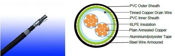
Conductor: Plain annealed copper wire, stranded according to IEC(EN) 60228 class 2 and 5 .
Insulation: Extruded cross-linked XLPE compound.
Overall Screen: Aluminium/polyester tape with 0.5mm2 screen (7/0.3mm) tinned copper drain wire.
Inner Sheath(optional): PVC compound
Armouring(optional): Galvanised steel wire
Outer Sheath: Thermoplastic PVC compound. UV resistance, hydrocarbon resistance, oil resistance,
anti rodent and anti termite properties can be offered as option. Compliance to fire performance
standard (IEC 60332-1, IEC 60332-3, UL 1581, UL 1666 etc) depends on the oxygen index of the
PVC compound and the overall cable design. LSPVC can also be provided upon request.
COLOUR CODE
Insulation Colour: See technical information
Outer sheath: Black or blue
Physical AND THERMAL PROPERTIES
Temperature range during operation: Max.90°C for XLPE
250°C in short-circuit for 5secs max.
Minimum bending radius: 8 x Overall Diameter (unarmoured cable)
10 x Overall Diameter (armoured cable)
CONSTRUCTION PARAMETERS
| Conductor | RE-2X(St)Y | RE-2X(St)YSWAY | ||||||
| No. of Core X Cross Section |
No./ Nominal Diameter of Strands |
Nominal Insulation Thickness |
Unarmoured | Armoured | ||||
| Nominal Overall Diameter |
Approx. Weight |
Diameter Under Armour |
Armour Wire Diameter |
Nominal Overall Diameter |
Approx. Weight |
|||
mm2 |
No./mm |
mm |
mm |
kg/km |
mm |
mm |
mm |
kg/km |
2x0.5 |
16/0.20 |
0.6 |
7.0 |
50 |
7.0 |
0.90 |
11.4 |
237 |
3x0.5 |
16/0.20 |
0.6 |
7.3 |
59 |
7.3 |
0.90 |
11.7 |
254 |
4x0.5 |
16/0.20 |
0.6 |
7.9 |
69 |
7.9 |
0.90 |
12.3 |
278 |
6x0.5 |
16/0.20 |
0.6 |
9.3 |
94 |
9.3 |
0.90 |
13.9 |
345 |
10x0.5 |
16/0.20 |
0.6 |
11.9 |
147 |
11.9 |
0.90 |
16.7 |
470 |
20x0.5 |
16/0.20 |
0.6 |
14.9 |
253 |
14.9 |
1.25 |
20.6 |
759 |
40x0.5 |
16/0.20 |
0.6 |
20.1 |
444 |
20.1 |
1.60 |
26.7 |
1229 |
2x0.75 |
24/0.20 |
0.6 |
7.3 |
57 |
7.3 |
0.90 |
11.7 |
251 |
3x0.75 |
24/0.20 |
0.6 |
7.7 |
68 |
7.7 |
0.90 |
12.1 |
272 |
4x0.75 |
24/0.20 |
0.6 |
8.3 |
81 |
8.3 |
0.90 |
12.9 |
310 |
6x0.75 |
24/0.20 |
0.6 |
9.9 |
114 |
9.9 |
0.90 |
14.5 |
379 |
10x0.75 |
24/0.20 |
0.6 |
12.7 |
179 |
12.7 |
0.90 |
17.5 |
522 |
20x0.75 |
24/0.20 |
0.6 |
16.0 |
311 |
16.0 |
1.25 |
21.7 |
858 |
40x0.75 |
24/0.20 |
0.6 |
21.7 |
555 |
21.7 |
1.60 |
28.5 |
1420 |
2x1.5 |
7/0.53 |
0.6 |
8.3 |
78 |
8.3 |
0.90 |
12.9 |
300 |
3x1.5 |
7/0.53 |
0.6 |
8.9 |
103 |
8.9 |
0.90 |
13.5 |
345 |
4x1.5 |
7/0.53 |
0.6 |
9.7 |
125 |
9.7 |
0.90 |
14.3 |
377 |
6x1.5 |
7/0.53 |
0.6 |
11.7 |
163 |
11.7 |
0.90 |
16.3 |
490 |
10x1.5 |
7/0.53 |
0.6 |
14.7 |
285 |
14.7 |
1.25 |
20.4 |
773 |
20x1.5 |
7/0.53 |
0.6 |
18.7 |
504 |
18.7 |
1.60 |
25.3 |
1262 |
40x1.5 |
7/0.53 |
0.6 |
24.6 |
935 |
24.6 |
1.60 |
31.6 |
1968 |