| Firetox Flame Retardant Cables | |||
![]() Firetox Flame Retardant Cables
Firetox Flame Retardant Cables
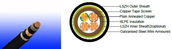
600/1000V XLPE Insulated, LSZH Sheathed, Screened Power Cables (4cores)FTX400 1RCZ1MZ1-R (CU/XLPE/CUTO/LSZH/SWA/LSZH 600/1000V Class 2) |
||||||||||||||||||||||||||||||||||||||||||||||||||||||||||||||||||||||||||||||||||||||||||||||||||||||||||||||||||||||||||||||||||||||||||||||||||||||||||||||||||||||||||||||||||||||||||||||||||||||||||||||||||||||||||||||||||||||||||||||||||||||||||||||||||||||||||||||||||||||||||||||||||||||||||||||||||||||||||||||||||||||||||||||||||||||||||||||||||||||||||||||||||||||||||||||||||||||||||||||||||||||||||||||||||||||||||||||||||||||||||||||||||||||||||||||||||||||||||||||||||||||||||||||||||||||||||||||||||||||||||||||||||||||||||||||||||||||||||||||||||||||||||||||||||||||
Flame Retardance (Single Vertical |
EN 60332-1-2; IEC 60332-1-2; BS EN 60332-1-2; VDE |
Reduced Fire Propagation |
EN 60332-3-24 (cat. C); IEC 60332-3-24; BS EN 60332-3-24; VDE 0482-332-3; NBN C 30-004 (cat. F2); NF C32-070-2.2(C1); CEI 20-22/3-4; EN 50266-2-4*; DIN VDE 0482-266-2-4 |
Halogen Free |
IEC 60754-1; EN 50267-2-1; DIN VDE 0482-267-2-1; CEI 20-37/2-1 ; BS 6425-1* |
No Corrosive Gas Emission |
IEC 60754-2; EN 50267-2-2; DIN VDE 0482-267-2-2; CEI 20-37/2-2 ; BS 6425-2* |
minimum Smoke Emission |
IEC 61034-1&2; EN 61034 -1&2; DIN VDE 0482-1034-1&2; CEI 20-37/3-1&2; EN 50268-1&2*; BS 7622-1&2* |
No Toxic gases |
NES 02-713; NF C 20-454 |
Note: Asterisk * denotes superseded standard.
VOLTAGE RATING
600/1000V
CABLE CONSTRUCTION
Conductor: Plain annealed copper wire, stranded according to IEC(EN) 60228 class 2.
Insulation: Extruded cross-linked XLPE compound.
Inner sheath1: LSZH Compound
Screen: Copper Tape
Inner sheath2: LSZH Compound
Armouring: Galvanised Steel Wire
Outer Sheath: Thermoplastic LSZH compound type LTS3 as per BS 7655-6.1 (Thermosetting LSZH
compound type SW2-SW4 as per BS 7655-2.6 can be offered.)
COLOUR CODE
Insulation colour as per bs7671
|
with earth conductor |
without earth conductor |
2Cores |
- |
Brown,Blue |
3Cores |
Yellow/Green,Brown,Blue |
Brown,Gray,Black |
4Cores |
Yellow/Green,Brown,Gray,Black |
Brown,Gray,Black,Blue |
5Cores |
Yellow/Green,Brown,Gray,Black,Blue |
Brown,Gray,Black,Blue,Black |
above 5 Cores |
Yellow/Green,Black Numbered |
Black Numbered |
sheath colour: Black
Physical AND THERMAL PROPERTIES
Temperature range during operation: Max.90°C for XLPE
250°C in short-circuit for 5s max.
Minimum bending radius: 12 x Overall Diameter (for 1.5mm2 to 300mm2)
CONSTRUCTION PARAMETERS
| Conductor | FTX400 1RCZ1MZ1-R | |||||||
| No. of Core X Cross Section |
No./ Nominal Diameter of Strands |
Nominal Insulation Thickness |
Nominal Sheath Thickness |
Diameter Under Screen |
Diameter Over Inner Sheath |
Armour Wire Diameter |
Nominal Overall Diameter |
Approx. Weight |
mm2 |
No./mm |
mm |
mm |
mm |
mm |
mm |
mm |
kg/km |
4x1.5 |
7/0.53 |
0.7 |
1.8 |
9.7 |
12.1 |
13.9 |
17.7 |
640 |
4x2.5 |
7/0.67 |
0.7 |
1.8 |
10.7 |
13.1 |
14.9 |
18.7 |
730 |
4x4 |
7/0.85 |
0.7 |
1.8 |
12.0 |
14.4 |
16.2 |
20.0 |
870 |
4x6 |
7/1.04 |
0.7 |
1.8 |
13.4 |
15.8 |
18.3 |
22.1 |
1180 |
4x10 |
7/1.35 |
0.7 |
1.8 |
15.6 |
18.0 |
20.5 |
24.3 |
1490 |
4x16 |
7/1.70 |
0.7 |
1.8 |
18.1 |
20.5 |
23.7 |
27.5 |
2070 |
4x25 |
7/2.14 |
0.9 |
1.8 |
22.3 |
24.1 |
27.3 |
31.1 |
2790 |
4x35(S) |
7/2.52 |
0.9 |
1.8 |
25.0 |
26.8 |
30.0 |
33.8 |
2940 |
4x50(S) |
19/1.78 |
1.0 |
2.0 |
27.8 |
29.6 |
32.8 |
37.0 |
3500 |
4x70(S) |
19/2.14 |
1.1 |
2.2 |
31.6 |
33.4 |
37.4 |
42.0 |
5000 |
4x95(S) |
19/2.52 |
1.1 |
2.3 |
35.4 |
37.2 |
41.2 |
46.0 |
6300 |
4x120(S) |
37/2.03 |
1.2 |
2.5 |
39.0 |
40.8 |
45.8 |
51.0 |
8200 |
4x150(S) |
37/2.25 |
1.4 |
2.6 |
42.0 |
43.8 |
48.8 |
54.2 |
9600 |
4x185(S) |
37/2.52 |
1.6 |
2.8 |
47.8 |
49.6 |
54.6 |
60.4 |
11500 |
4x240(S) |
61/2.25 |
1.7 |
3.0 |
54.0 |
55.8 |
60.8 |
67.0 |
14400 |
4x300(S) |
61/2.52 |
1.8 |
3.0 |
58.0 |
59.8 |
64.8 |
71.4 |
17200 |
Electrical PROPERTIES
Conductor Operating Temperature : 90°C
Ambient Temperature : 30°C
Current-Carrying Capacities (Amp)
Conductor |
Reference Method 1 (clipped direct) |
Reference Method 11 (on a perforated horizontal cable trayor Reference Method 13 [free air] ) |
In single-way ducts |
Laid direct in ground |
||||
one |
one |
one |
one |
one |
one |
one |
one |
|
1 |
2 |
3 |
4 |
5 |
6 |
7 |
8 |
9 |
mm2 |
A |
A |
A |
A |
A |
A |
A |
A |
1.5 |
27 |
23 |
29 |
25 |
- |
23 |
- |
28 |
2.5 |
36 |
31 |
39 |
33 |
- |
30 |
- |
36 |
4 |
49 |
42 |
52 |
44 |
- |
40 |
- |
48 |
6 |
62 |
53 |
66 |
56 |
- |
50 |
- |
60 |
10 |
85 |
73 |
90 |
78 |
- |
65 |
- |
80 |
16 |
110 |
94 |
115 |
99 |
115 |
94 |
140 |
115 |
25 |
146 |
124 |
152 |
131 |
145 |
125 |
180 |
150 |
35 |
180 |
154 |
188 |
162 |
175 |
150 |
215 |
180 |
50 |
219 |
187 |
228 |
197 |
210 |
175 |
255 |
215 |
70 |
279 |
238 |
291 |
251 |
260 |
215 |
315 |
265 |
95 |
338 |
289 |
354 |
304 |
310 |
260 |
380 |
315 |
120 |
392 |
335 |
410 |
353 |
355 |
300 |
430 |
360 |
150 |
451 |
386 |
472 |
406 |
400 |
335 |
480 |
405 |
185 |
515 |
441 |
539 |
463 |
455 |
380 |
540 |
460 |
240 |
607 |
520 |
636 |
546 |
520 |
440 |
630 |
530 |
300 |
698 |
599 |
732 |
628 |
590 |
495 |
700 |
590 |
Voltage Drop (Per Amp Per Meter)
Conductor cross- sectional area |
2-core cable d.c. |
2 cables, single-phase a.c. |
3 or 4 cables, 3-phase a.c. |
2 cables, single-phase a.c. |
3 or 4 cables, |
||||
In ducts or in ground |
In ducts or in ground |
||||||||
1 |
2 |
3 |
4 |
5 |
6 |
||||
mm2 |
mV/A/m |
mV/A/m |
mV/A/m |
mV/A/m |
mV/A/m |
||||
1.5 |
31.0 |
31.0 |
27.0 |
31.0 |
25.0 |
||||
2.5 |
19.0 |
19.0 |
16.0 |
19.0 |
15.0 |
||||
4 |
12.0 |
12.0 |
10.0 |
12.0 |
9.7 |
||||
6 |
7.9 |
7.9 |
6.8 |
7.9 |
6.5 |
||||
10 |
4.7 |
4.7 |
4.0 |
4.7 |
3.9 |
||||
16 |
2.9 |
2.9 |
2.5 |
2.9 |
2.6 |
||||
|
|
r |
x |
z |
r |
x |
z |
|
|
25 |
1.850 |
1.350 |
0.160 |
1.900 |
1.600 |
0.140 |
1.650 |
1.900 |
1.600 |
35 |
1.350 |
1.350 |
0.155 |
1.350 |
1.150 |
0.135 |
1.150 |
1.350 |
1.200 |
50 |
0.980 |
0.990 |
0.155 |
1.000 |
0.860 |
0.135 |
0.870 |
1.000 |
0.870 |
70 |
0.670 |
0.670 |
0.150 |
0.690 |
0.590 |
0.130 |
0.600 |
0.690 |
0.610 |
95 |
0.490 |
0.500 |
0.150 |
0.520 |
0.430 |
0.130 |
0.450 |
0.520 |
0.450 |
120 |
0.390 |
0.400 |
0.145 |
0.420 |
0.340 |
0.130 |
0.370 |
0.420 |
0.360 |
150 |
0.310 |
0.320 |
0.145 |
0.350 |
0.280 |
0.125 |
0.300 |
0.350 |
0.300 |
185 |
0.250 |
0.260 |
0.145 |
0.290 |
0.220 |
0.125 |
0.260 |
0.290 |
0.250 |
240 |
0.195 |
0.200 |
0.140 |
0.240 |
0.175 |
0.125 |
0.210 |
0.240 |
0.210 |
300 |
0.155 |
0.160 |
0.140 |
0.210 |
0.140 |
0.120 |
0.185 |
0.210 |
0.190 |